Hellllooooo everyone!
I’m alive, again. Maki asked me to make a blog post about how we changed the MSX HitBit T7 japanese power supply unit (from now on PSU) for a more modern and european one. So, let’s do this.
Update (2020-05-29): Victor Muñoz tutorial
Victor Muñoz followed this post (plus the discussion we have had on email) and did this mod. He has shared with me a PDF containing the tutorial he has made. So check this for additional notes and photos so it’s clearer.
Click here to read it! (In Spanish)
Bill of materials
- A power supply unit (PSU) (+12v, -12v and +5v) [In our case a Traco Power 60 TOP 60522, the one that gives us those voltages]
- A 3 pin and 6 pin molex connector. They are those that you can see connected to the power unit board.
- Cables. If my memory doesn’t fail me, you won’t be needing them as the already present ones can be reused. But have some cables at hand, just in case.
- Screws with nuts to hold the power unit board to the chassis.
- A lighter and something round and metalic to heat it… or a dremel to perforate the chassis for the screws.
- Soldering iron and solder metal (I don’t remember the name in english right now)
- You may need a dremel or something to cut some metallic part so that the PSU fits
- Plugs to adapt your MSX cable
First contact
First of all, when you open the MSX and remove the keyboard (god, that keyboard connector sux a lot) you’ll see something like this:
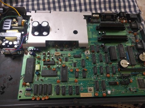
You may have noticed a couple of changes: You’ll have a japanese PSU and you may have different batteries.
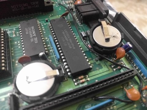
Instead of two button batteries you should have one button battery and a barrel one, for the modem and the BIOS respectively (If I’m not wrong!). REMOVE THE BARREL ONE ASAP. It may led your board to corrosion when it explodes. You can change it for another compatible rechargeable battery or use a diode to lower the voltage of a button one and cut the power in one-way so that the battery doesn’t get to recharge (if you charge a non-rechargeable battery you may have problems :)). Thanks to Ronivon Costa for this diode trick!
Operation details and overview
This is our target:
We need to do the following steps:
1) Remove the old PSU (cut and desolder)
2) Cut the wires from the old PSU to reuse them
3) Calculate where to put the new PSU
    + Do holes on the chassis so we can put the screws to hold the PSU there
    + You may have to cut part of the metal below the old PSU
    + You may also have to cut the plastic holders that held the old PSU so you
      can fit the PSU
4) Secure the new PSU in place
5) Remove 3 components to solder our PSU cables directly to their output
6) Build the PSU cables with the required length to reach everywhere
    + Mind that the 6 pin one needs to be long, try to plan it well. These
      cables should be in the place where the 3 removed components were
7) Solder everything up
Notice that I only have pictures of the MSX completed. I had pictures of the operation day but I’m not able to find the.
The PSU
First of all we have to check how to plug the things. If you bought the same PSU as I did, you have the manual here.
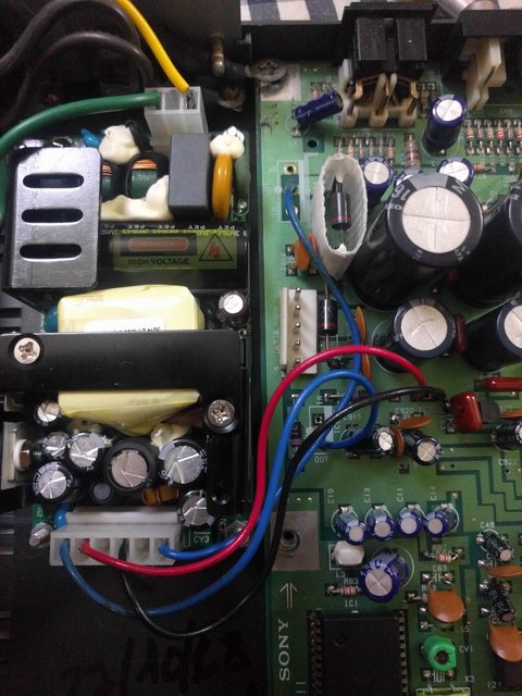
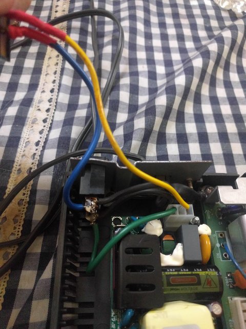
So, from the last picture from left to right:
- Blue: 12v
- Red: -12v
- Black: Ground
- Blue: 5v
Yes, we could have used a different color for 5v, but that was what we had!
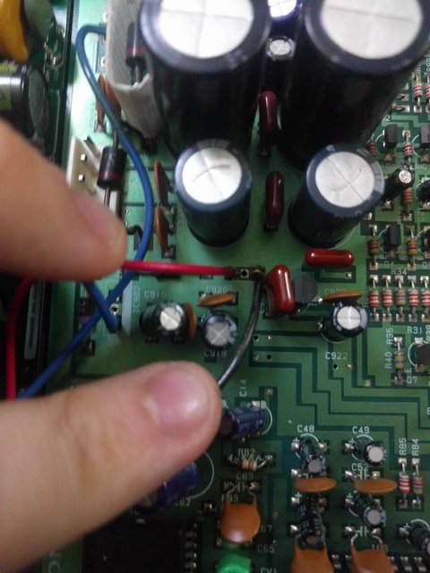
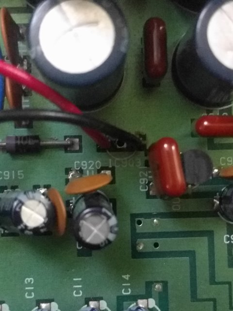
-12v and ground
We soldered both the ground and -12v to component IC903 place. You could solder the ground in other places, but we thought that this one was practical.
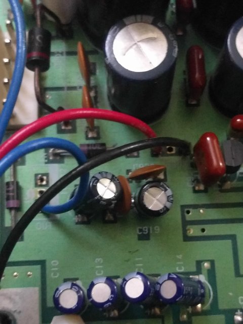
+12v
This is where you connect the 12v (blue cable):
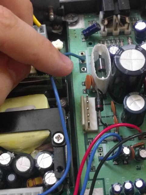
+5v
This is where you connect the 5v:
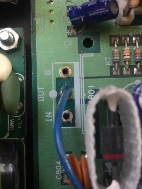
Power input
Finally, the power input should be soldered like this:
Notice that it doesn’t matter which pin is soldered to where as we’re dealing with alternating current (AC).
Screws
In my case, the screws were setted up as follows:
Final touches
Finally, you’ll need to cut the power cable to adapt it to your regional plug!
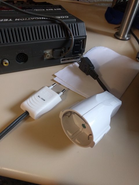
And if you want it, you can use the japanese plug to create an adapter so you can use your MSX back plug as it now runs at your voltage.
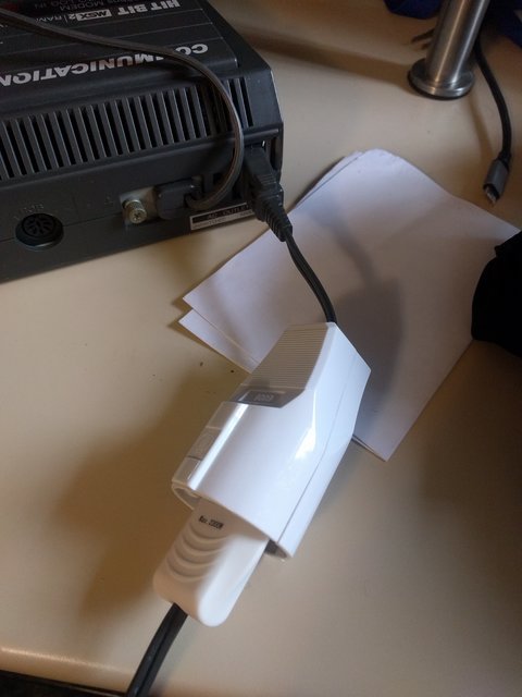
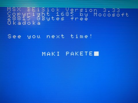
And it works!
Optional steps
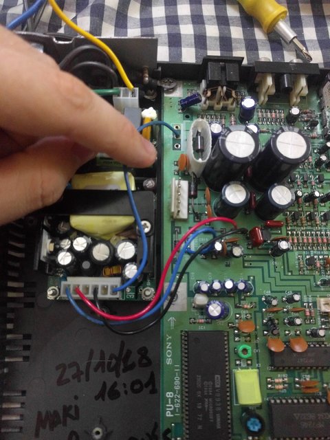
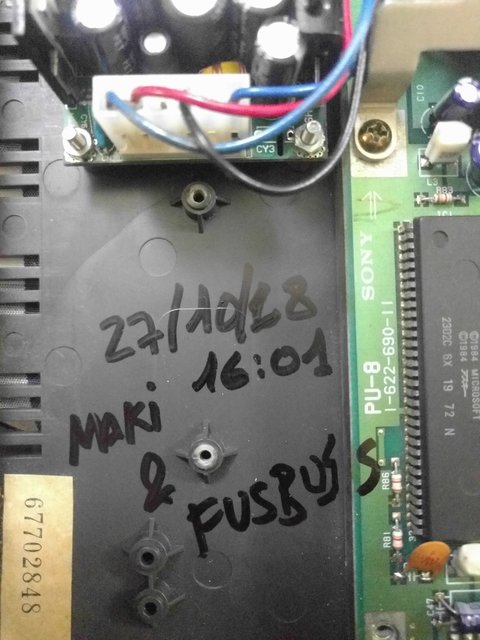
You may want to remember when did you made the mod, with who you where and where was it, so write it down inside your MSX!
Closure
Thanks to JamQue for his idea of using molex conectors instead of soldering stuff directly. Thanks to Maki for all his support and knowledge during all the operation :).